Description
Sulzer regulators are well known and proved their efficiency over the years. Schematic offered here is slightly modified two-polarity Sulzer regulator which has some improvements over original one:
1. Active regulation elements (opamps U1 and U2) are supplied by capacitive multipliers Q1, R3, C5 and Q2, R4, C6 for negative rail respectively.
2. Reference voltage sources (Zener diodes D14 and D15 resp.) are placed on the right (stabilized) sides of the regulators which ensures much more lower noise over them.
3. Diodes D11, D12 ensure normal start of the two rails no matter what load is connected.
That schematic has very good capabilities (both simulated and measured) for ripple and noise suppression.
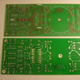
PCB for the schematic is with dimensions 130×80 mm.
PCB thickness: FR4 1.55 mm. Copper thickness: 35um (1oz). Surface finish – Nickel Gold (ENIG).

As it’s seen from the picture, this new version has the possibility for using bigger main filter electrolytic capacitors, bigger heatsinks for the regulation transistors, bigger terminal blocks for more convenient wiring etc.
The board is possible to work with transformers with two separated secondary windings or with one secondary with centertap.
The new board has incorporated protection circuitry for each rail, which allow to limit the output currents.
PCB has following abilities:
– places for rectifier diodes with different cases – DO41, SOD-57, DO-201.
– places for main filter capacitor with different sizes – radial leaded with lead spacing of 7.5mm or snap-in with lead spacing 10mm. and outer diameter 30mm. max.
– holes for mounting different types of heatsinks.
– resistors R9, R12 can be RM10 or RM15 lead spacing (depending on its desired power rating).
– output current limiting network (Q3, R7, R10 and Q6, R8, R11) which ensures the SOA (safety area of operation) of the regulation transistors Q3 and Q4.
– both output rail voltages can be fine-tuned with the trimmer-resistors R14, R15.

All parts used are easily obtainable from big supplier stores (Mouser, Farnell, Digi-Key etc.) or via e-bay.
Performance of the unit was measured using RTX6001 spectrum analyzer at 12V/1A:

The regulator can work in 5 – 30V range.
Schematic and parts list will be sent to the buyer’s email address after purchase. If for some reason a different email address must be used, note it in the process of checkout.
Note: The pictures of the assembled board are for information purposes only!
What the buyer will receive:
The package will contain 1 pcs. PCB for modified Sulzer regulator v.4 – Dual Channel.
Submit your review | |